※ Pinhole dimension 4 / 15 / 80 stands for ; 4 holes of 15㎜ diameter located on a PCD 80 ㎜
Main Tooth Geometry
TC + FT Tooth
Combined the Triple Chip and Flat Top Tooth.Breaks up the chips and stabilizes the blade while cutting operation. Suitable for cutting ferrous solid bars,billets and non ferrous material.
Flat Top Tooth with Notching
Flat Top Tooth geometry is the most effective in cutting.The notch on the OD breaks up the chips and its removal.Suitable for cutting thick walled metal tube / pipeand structual section.
TC + FT corner breaks Tooth
Combined the Triple Chip and Flat Top corner break Tooth.Breaks up the chips and stabilizes the blade while cuttingoperation. Flat Top corner break tooth for strengthen the outsidecutting edge of carbide to prevent breakage. Suitable for cuttingmedium carbon steel plate & stainless steel plate.
ATB Tooth
Alternate Top Bevel Tooth geometry provides high shear cutting.Effective where close tolerances are required.Suitable for cutting thin walled non-ferrous profiles & tubes.
ATB Tooth with corner break
Modified the corner of Alternate Top Bevel Tooth geometry reduces the weakness of sharp carbide edge.Suitable for cutting thin walled non-ferrous profiles & tubes.
TC + Transform ATB Tooth
Special 3 tooth tooth geometry reduces the cutting pressures and stabilizes the blade in cutting operation.Obtain smooth surface finish.Suitable for cutting non-ferrous metal plate where better finish required.
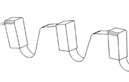
Hook Angle
Positive Hook angle
The teeth are tipped forward in line with the center of the saw blade,toward the direction of the saw blade's rotation.In general, positive hook angle suitable for fast feedingand standard hook angle ranges from 5° to 15° positive.
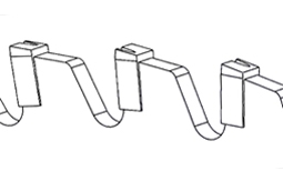
Negative Hook angle
The teeth are tipped backward in line with the center of the saw blade.Usually - 5° are used with lower feed rate.In general, suitable for metal cutting application.
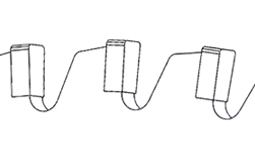
Zero Hook angle
The teeth are in line with the center of the saw blade.
Cutting Parameter Calculation Formula
1. Cutting speed(Vc ; Cutting Speed) shows as M/min or M/sec
Vc =
π × D × N
1000
(M/min)
or
Vc =
π × D × N
60×1000
(M/min)
※ π : 3.14159 / D : Saw blade diameter (㎜) / N :RPM
Vc =
3.14159 × 350 × 230
1000
252.97 M/min
or
Vc =
3.14159 × 350 × 230
60×1000
4.215 M/sec
Calculation example / When D; 350㎜, N; 230rpm, then the Cutting speed will be ;
2. Feed speed vs Feed rate
(Fz : Feed rate, Feed /teeth or Chip Load)
A correct feed per tooth (Fz) is required to optimize the saw blade's tool life and cutting performance. When Fz value is too low, it could cause rapid wear of cutting edge. When Fz value is too high, it could cause tooth breakage.
Vf =
Fz × N × Z
1000
(M/min)
※ Fz : Feed Rate / Feed per Tooth (㎜) or Chip load / tooth / N : RPM / Z : Number of teeth / Vf : Feed speed (M/min)
Vf =
Fz × N × Z
1000
0.966 M/min
Calculation example / When D; 350㎜, N; 230rpm, Fz=0.035㎜, Z=120, then the Feed speed will be ;
3. Tooth Pitch calculation
Tp =
π × D
Z
※ Tp : Tooth Pitch / π : 3.14159 / D : Saw blade diameter(㎜) / Z : Number of teeth
Tp =
3.14159 × 350
120
9.16mm
Calculation example / When D; 350㎜, N; 230rpm, Fz=0.035㎜, Z=120, then the Tooth pitch will be ;
※ In general, increase the number of tooth enables clean surface cut. When cutting thick material, choose larger tooth pitch.
Recommended Cutting Speed
1.
Recommended Cutting speed & Feed Rate for different material
Cutting material
Cutting speed Vc(m/sec)
Feed rate Fz (㎜/tooth)
Soft wood
60 - 100
0.2 - 0.3
Hard wood
50 - 85
0.06 - 0.15
Plywood
50 - 85
0.02 - 0.12
Verneer
60 - 100
0.3 - 0.7
MDF / HDF
50 - 80
0.1 - 0.3
Plastic
20 - 70
0.02 - 0.1
PCB
45 - 65
0.01 - 0.03
Aluminium
60 - 80
0.03 - 0.10
Copper
50 - 70
0.03 - 0.08
Brass
50 - 70
0.03 - 0.08
2.
Recommended Cutting speed & Feed Rate for Metal
[Solid Material]
Cutting material
Tensile strength(N/㎟)
Cutting speed Vc(m/min)
Feed rate Fz(㎜/tooth)
Mild steel
< 500
180 - 250
0.05 - 0.08
Carbon steel
500 - 750
100 - 200
0.03 - 0.06
Alloy steel
750 - 950
180 - 250
0.03 - 0.08
High tension steel
950 - 1200
100 - 200
0.025 - 0.06
Austenite Stainless steel
500 - 800
50 - 70
0.04 - 0.06
Ferrite Stainless steel
400 - 700
60 - 80
0.05 - 0.07
[Tube / Pipe]
Cutting material
Tensile strength(N/㎟)
Cutting speed Vc(m/min)
Feed rate Fz(㎜/tooth)
Mild steel
< 500
100 - 220
0.03 - 0.15
Carbon steel
500 - 750
150 - 350
0.03 - 0.10
Alloy steel
750 - 950
100 - 250
0.03 - 0.08
High tension steel
950 - 1200
30 - 130
0.025 - 0.06
Austenite Stainless steel
500 - 800
30 - 80
0.04 - 0.06
Ferrite Stainless steel
400 - 700
40 - 80
0.04 - 0.07
Basic Information
1. Clamping stability of saw blade and cutting material
A stable circular saw blade is the most important factor for obtaining good cutting results. Stability should be necessary at the machine main bearing, spindle and clamping device. Insufficeint stability generates vibration at the machine and/or saw blade and leads to serious loss of tool life and saw blade breakage. Also the cutting material must be fixed perfectly, especially when cutting various profile shape tubes, special formed fixture is highly recommended.
2. Cleaning before saw blade mounting
Thorough cleaning of the saw blade and flange before mounting is very esential and important. Even single chip between the saw blade and flange may ause of excessive side run out as well as machine stabilty and cut quality.
3. Remove Backlash in Pinhole area
When mouning the saw blade equipped with pinholes, backlash in the pinholes must be removed before tightening the saw blades with flanges. Putting slight pressure against front face of saw body in a reverse direction of the saw blade rotation and tightening the pinhole bolts/ screws. Failure to remove this backlash may cause of saw blade breakage.
4. Running In
Recommend to conduct "Running in" procedure for obtaining the longer tool life when use new / re-sharpened saw blade as below. ① Make around 10 cuts at normal RPM with at only 25 ~ 50 % of normal feed rate. ② Gradually increase the feed rate until reached to normal feed rate. Above procedure could removes the sharp edges of tooth tips and thus increasing tool life.
5. Saw blade breakage
- Saw blade has too many tooth for current cutting application - Fz is too high (Fz : Feed rate, Feed/tooth or chip load/tooth) - Insufficient clamping of cutting material - Cutting speed is too high - Check the blade rotation direction - normal or reverse direction
6. Tooth breakage - Cutting edge breakage
- When the chips sticks to the tooth front face, generates excess cutting pressure on the cutting edge and leads to tooth breakage. Remove these chips by install wire brush, air gun or using cuting fluid. - Use more bigger tooth pitch saw blade. More space between the teeth could improve chip sticking problem. - Vibration from the saw blade and/or cutting material leads to tooth breakage. - Improve clamping device of cutting material for perfect clamp. - Check the machine bearing status, spindle bent status. - Consider to change tooth geometry.
7. Cutting quality
[ Inside burr ] ① Cutting edge worn out ② Incorrect tooth geometry ③ Incorrect tooth pitch - Tooth pitch is too big ④ Saw blade vibration - Check the cuttingmachine condition & Saw blade stability
[ 외부 Burr 발생원인 ] ① Cutting edge worn out ② Incorrect tooth geometry ③ Fz is too low(Fz : Feed rate, Feed/tooth or chip load/tooth) ④ Cutting speed is too high
[ 절단표면 이상 ] ① Surface scratched - Some tooth damaged ② Rough surface - Vibration : Incorrect cutting parameters (change cutting speed and/or feed rate) Incorrect saw blade (change saw blade type and/or tooth geometry) - Wave - increase feed rate - Rough wave - increase cutting speed
8. Chip Formation
① Feed rate ( Fz ) is too lowGenerates improper chip formation like metal powder status. The blades worn out very rapidly and blade life is reduced significantly. ② Feed rate ( Fz ) is too highDiscolored chip may sticking at gullet area. High risks of blade breakage. ③ Feed rate ( Fz ) is optimalChips are well rounded, uniform status with bright color. Maximum tool life and longer use.
.jpg)


.svg)
